Previous Article in Journal
Artificial Intelligence in Predicting Mechanical Properties of Composite Materials
 
 
Order Article Reprints
Article

Adjunctive Damage Model to Describe the Interaction of Different Defect Types in Textile Composites on the Strain-Rate-Dependent Material Behaviour

Institute of Lightweight Engineering and Polymer Technology (ILK), Technische Universität Dresden, Holbeinstraße 3, 01307 Dresden, Germany
*
Author to whom correspondence should be addressed.
J. Compos. Sci. 2023, 7(9), 365; https://doi.org/10.3390/jcs7090365 (registering DOI)
Received: 12 July 2023 / Revised: 22 August 2023 / Accepted: 29 August 2023 / Published: 1 September 2023
(This article belongs to the Section Composites Modelling and Characterization)

Abstract

:
Textile composites are predestined for crash-loaded lightweight structures due to their adjustable energy absorption capacity, but they can exhibit different types of defects that occur during production (voids) and in operation (fatigue). The influence of such defects, especially the interaction of several defect types on the strain-rate-dependent material behaviour, is still insufficiently researched and can represent a safety risk. Therefore, this paper presents a phenomenological model that can be used to mathematically describe the strain-rate-dependent stress-strain behaviour of nominally defect-free and defect-affected textile composites. An adjunctive damage model in the sense of continuum damage mechanics is introduced, which also considers the interaction of both defect types for the first time. For the model validation, extensive experimental tests on glass fibre non-crimp fabrics reinforced epoxy (GF-NCF/EP) composites are performed. The focus is put on the influence of voids and fatigue-related pre-damage under subsequent tensile loading at strain rates up to 40 s 1 . The theoretical studies show a good coincidence with the experimental results. The novel model provides a method for the efficient generation of material maps for numerical highly dynamic crash and impact analyses for defect-free and defective textile composites. As a result, a flexible and practice-oriented model approach is available, which makes a significant contribution to an improved understanding of materials and enables a future defect-tolerant design of textile composites.

1. Introduction

Due to their adjustable energy absorption capacity, non-crimp fabric composites (NCF-composites) are predestined for lightweight structures that are exposed to high deformation rates during their use [1,2]. NCF-composites can be compromised by defects that arise during manufacture, like voids [3,4] and fibre misalignments [5,6,7]. However, defects can also occur during product use, such as fatigue [8,9,10] or impact [11,12,13]-induced cracks (further on referred to as service-related defects).
Voids are the most common defects in composites [14,15]. Their formation depends on the selected manufacturing process and is described in detail in [16,17] for the prepreg process and in [3] for the infiltration process. Other studies focus on investigating the influence of voids on material behaviour [3,18]. Furthermore, there is a growing number of approaches for the mathematical description of the defect influence on the mechanical properties [19,20,21]. In experimental investigations, the focus is put on the influence of voids on the mechanical properties of materials under creep [18,22], quasi-static [23,24,25], cyclic [7,26,27,28], and highly dynamic [28] loading. These studies describe the degradation of stiffness and strength as a function of porosity.
For example, in [24], the tensile, flexural, and interlaminar shear strengths of unidirectional (UD) carbon fibre-reinforced epoxy samples were reduced by deliberately creating void contents of 0.03% to 6.25% using blowing agents. The author reports that the tensile strength is reduced by 10% for void contents up to 2.3% compared to void-free laminates. However, the degradation rate decreases with higher void contents.
The influence of voids on the fatigue behaviour of glass fibre NCF-reinforced epoxy resins with [0/+45/90/−45]as layer structure under uniaxial loading was investigated in [16]. During the injection moulding process, the authors introduced air into the liquid matrix via a bypass, resulting in void volume contents between 2.5% and 8.8%. Under both tensile–tensile and compression–compression fatigue, a decrease in lifetime was demonstrated for the porous material.
It was found in [29] that the stiffness and strength of carbon fibre-reinforced epoxy resin with void contents of up to 5% were not affected when subjected to quasi-static tensile loading. However, when tested under pulsating tensile load, the lifetime, stiffness, and crack initiation stress are reduced. Especially in the layer with a reinforcement perpendicular to the loading, a higher crack density is measurable here. But despite that, the influence of voids on crack density and stiffness decreases with increasing load cycles.
Approaches for the mathematical description of the influence of voids on the resulting material properties can be found in [19,20,21,30]. They are based on phenomenological approaches as well as on micromodels [30] and homogenisation concepts for porous materials [31,32].
Among others, in [33] an extended mixing rule is established for UD-layers to calculate the stiffness in the fibre direction as well as perpendicular to the fibre direction depending on the void volume fraction. But, only the reduced longitudinal stiffnesses can be predicted with sufficient accuracy.
A representative volume element (RVE) for UD-layers with typical occurring void geometries was developed and described in [34]. The results of a parametric study predict a strong void influence on the out-of-plane stiffnesses, while the in-plane properties are less affected. It was found that the shape and size of the voids have different effects on the individual directional stiffnesses. For example, elongated flat voids mainly reduce the shear moduli G 13 and G 23 , whereas the in-plane shear modulus G 12 is hardly affected.
In [19], RVEs were used to account for idealised ellipsoidal voids and computed tomography (CT) images were used for real void morphologies. Thus, the authors calculated a negative influence of voids on the normal- and shear-components of the stiffnesses in the laminate thickness direction.
In [35], the influence of voids on the quasi-static material behaviour is also investigated with the help of RVE. In addition to the fibre and the matrix, the unit cell also contains an adjective for description of the shape of micro voids between the filaments and spherical macro voids between the rovings. The material behaviour under transverse tensile and compressive loading was simulated.
To assess the influence of service-related defects, the resulting stiffness behaviour [36,37,38] and strength behaviour [9,39,40] are primarily analysed in the literature with models for predicting the residual stiffness due to cyclic preloading based on probabilistic [36] or phenomenological [37,38] approaches. For example, in [37], a model for predicting residual stiffness after fatigue loading with both constant amplitude and service loading is presented. In this model, damage parameters are defined that depend on the material as well as on the pre-fatigue and are obtained from experiments by using the least squares method. Based on investigations of glass fibre and carbon fibre-reinforced epoxy composites with five different layer structures each, the authors showed a higher fatigue-related stiffness decrease for epoxy with glass fibre reinforcement than with carbon fibre reinforcement.
In general, fibre reinforced composites show a considerable residual load-bearing capacity, even after an initial failure in the form of inter-fibre fracture or delamination [41,42]. In addition, basic analyses of the interaction of service-related defects under different types of cyclic loading are known from fatigue tests. For example, the residual strengths after cyclic loading are examined and described by means of wear-out or sudden-death models in [43], who describe a statistical model based on RVEs for predicting the residual strength and the service life of fibre composite materials under cyclic loading. The decrease of the residual strength is shown and the probability of failure is given. In [44,45,46], the residual strength degradation of composites is investigated and models are established based on the number of cycles and the maximum stress that occurs. In [40], the authors validate several known phenomenological residual strength models using experimentally determined residual strengths after cyclic preloading. For this purpose, the models are adapted for enabling statistical predictions of the residual strengths at different load levels for different materials and laminate structures. However, due to the large scatter of the measured values, which increases further with increasing pre-fatigue [9] and can be attributed to the initiation and evolution of different damage mechanisms, they cannot provide a conclusive evaluation in the comparison of the model approaches. Only with the easily feasible linear degradation model of Broutman and Sahu [47] can residual strengths be modelled appropriately and conservatively throughout [40].
Investigations on the influence of voids on the strain-rate-dependent material behaviour of FRP have been presented by the author in [28]. The first approaches for modelling the strain-rate-dependent deformation behaviour have been published for glass-fibre-reinforced thermoplastics [10,48,49] and thermosets [8,50,51]. Potentially existing defects due to previous damage caused by service loads are only considered in [10]. In summary, the studies on the influence of defects on material behaviour always focus on one type of defect (voids or pre-fatigue). However, in practice, different types of defects can occur simultaneously and influence each other [4,52]. The effects of several defect types on the strain-rate-dependent material behaviour of NCF-composites were first investigated and mathematically described in [8]. In the developed damage model, sequential damage due to defects from manufacturing (voids) and in subsequent service (fatigue) is taken into account by adding up the individual damage parameters. However, this model does not take into account interactions between defect types as demonstrated in [4] using in situ computed tomography studies. Based on this work, the model of [8] has been refined and is presented in this paper.

2. Materials and Methods

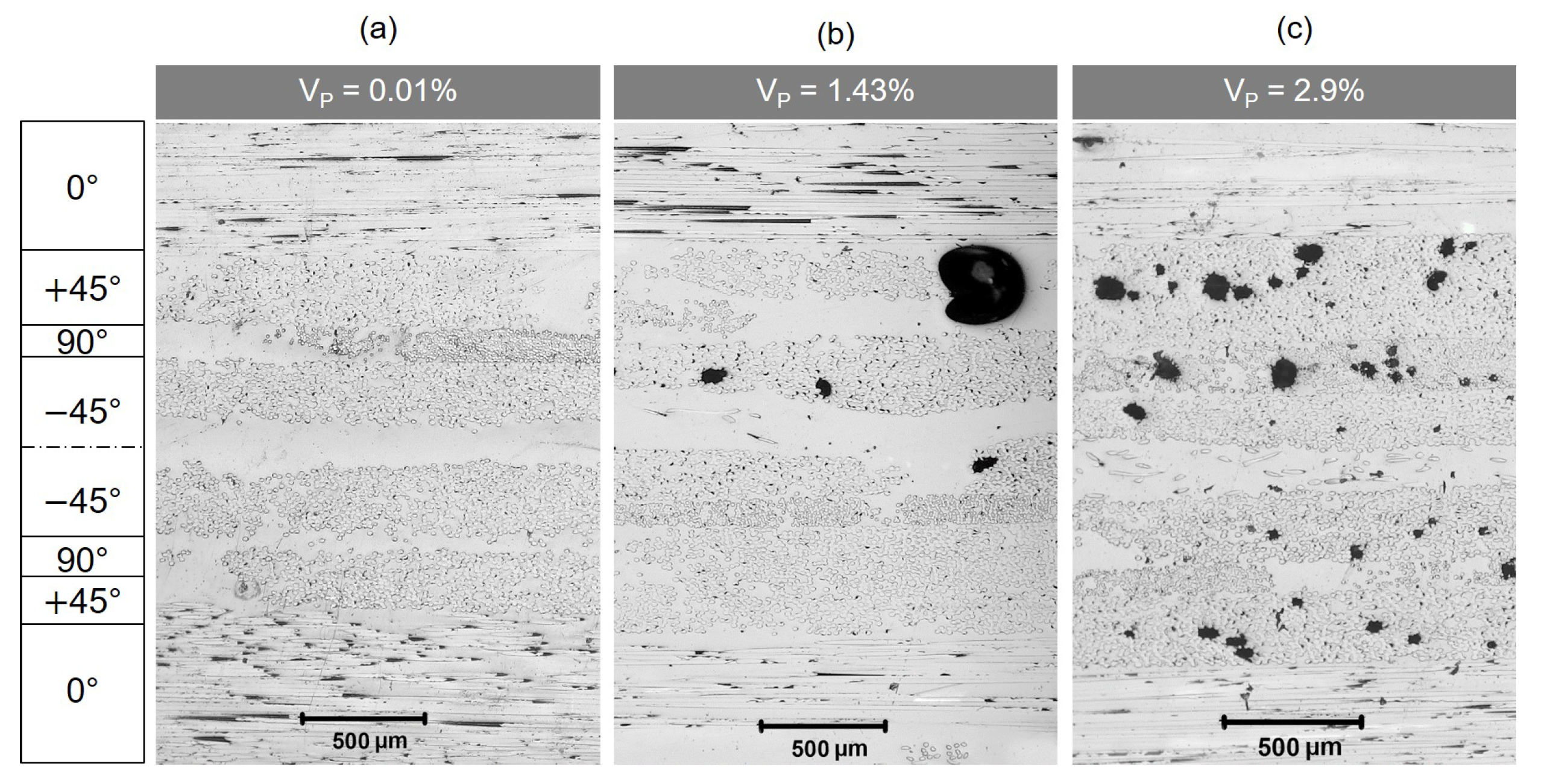
2.1. Materials and Pre-Damaged Methods

For the experimental studies, composites with glass fibre non-crimp fabric reinforcement (GF-NCF) of eight layers [ 0 / + 45 / 90 / 45 ] s are considered. The plies are characterised by different fibre mass fractions (49% in 0°, 23% in 45°, 23% in −45°, and 5% in 90°). Using the vacuum-assisted resin transfer moulding (VARTM) method, test plates were infiltrated in a flat steel mould with a cavity height of 3 mm. The injection resin RIMR 135 with hardener RIMH 137 in a ratio of 100:30 was used. This resin has a low viscosity and is cold curing within 24 h. For the purpose of reducing the process time, the infiltration as well as curing is carried out at 40 °C. A curing time of 10 h is followed by a temper cycle of 6 h at 80 °C. After the heat treatment, the resin shows a glass transition temperature of 85 ± 2 °C, measured by the dynamic different calorimetry according to ISO 11357. A fibre volume fraction of about 34.4 ± 3% has been achieved according to ISO 1172. To investigate the influence of voids, the VARTM-complex was instrumentally equipped with electronic pressure sensors and an instrumented resin trap in order to be able to set the process parameters specifically. The main parameters influencing the void content ( V P ) are the injection pressure on the resin inlet and the vacuum on the resin outlet. The infiltration of test plates was always started at atmospheric pressure followed by an increase to the desired infiltration pressure level and maintaining the pressure level until the fluid reaches the resin outlet. In the case of holding pressure, the final infiltration pressure is maintained until the resin system is fully cured. The resin-hardener mixture is only degassed for the production of the nominally defect-free reference specimens before infiltration. Table 1 contains the process parameters for the production of test specimens with defined void content as well as nominally defect-free reference specimens. This provides test plates with voids contents of 0.01 ± 0.01%, 1.43 ± 0.65%, and 2.9 ± 0.9%. All plates are computed tomography scanned as described in [4].
The different void contents of the three configurations are also clearly visible in the micrographs in Figure 1. The reference specimen (Figure 1a) is almost defect-free, only smaller voids are visible. Larger spherical voids in the intermediate fibre areas and smaller voids in the fibre areas are visible in the specimens with low void content (Figure 1b). The micrographs of test specimens with higher void content show clearly more voids with in the fibre rovings. (Figure 1c). In the upper layer, tubular voids are often visible, oriented in the direction of the fibres. The majority of the voids are found in the 45°-layers.
After infiltration and curing, test specimens were extracted from the manufactured plates in angles of 0°, 45°, and 90° by water jet cutting. The sample dimensions are 250 mm in length, 25 mm in width, and 3 mm in thickness. In order to analyse the influence of fatigue-related pre-damage on the material behaviour, specimens have been fatigued with an uniaxial cyclic testing machine with a maximum stress of 60% of the orientation specific quasi-static tensile strength, at a load ratio of R = 0.1 and a frequency of 4 Hz under ambient conditions. During uniaxial cyclic loading, material degradation occurs, which is manifested, among others ways, by the formation and growth of cracks in the matrix [53] and manifests itself in a drop in the dynamic stiffness E d y n , which is defined as the constant slope between the extreme values of the stress-strain hysteresis [44]. The change in dynamic stiffness is used in the following as a reproducible fatigue-related defect of the material. From the ratio of the dynamic stiffness to the initial stiffness E 0 , the cyclic material damage parameter D c y is defined as follows
D c y = 1 E d y n / E 0 .
To determine the influence of fatigue-related pre-damage on the strain-rate-dependent material behaviour, fatigue experiments were stopped after a short period of time ( D c y = 0.29 ) , while others were continued for longer periods ( D c y = 0.42 ) . Void-containing test specimens were also fatigued up to the same shutdown criterion with regard to analysing the interaction of manufacturing-related (voids) and service-related (fatigue) defects on the strain-rate-dependent material behaviour.
A servo-hydraulic high velocity test rig INSTRON VHS 160/20 is used for the characterisation of the strain-rate-dependent material behaviour of the GF/NCF-EP-composite. The test rig is capable of generating a maximum test force of 160 kN and test speeds of up to 20 m/s and thus allows determining the strain-rate-dependent material behaviour of the GF/NCF-EP-composites with strain rates ( ε ˙ ) in the range between 0.0004 s 1 and 40 s 1 . For highly dynamic tensile tests, the VHS is equipped with a special clamping device that allows impulse-like force application into the specimen, thus ensuring tensile tests with constant strain rates. The deformation measurement is carried out by means of digital image correlation (GOM, Aramis), which requires the preperation of specimens with a grey scale point pattern. The distortion of the point pattern during tensile loading is recorded with a high-speed camera and then analysed with the Aramis software. For further information on the measurement principle and evaluation procedures of highly dynamic experiments, please refer to [48].

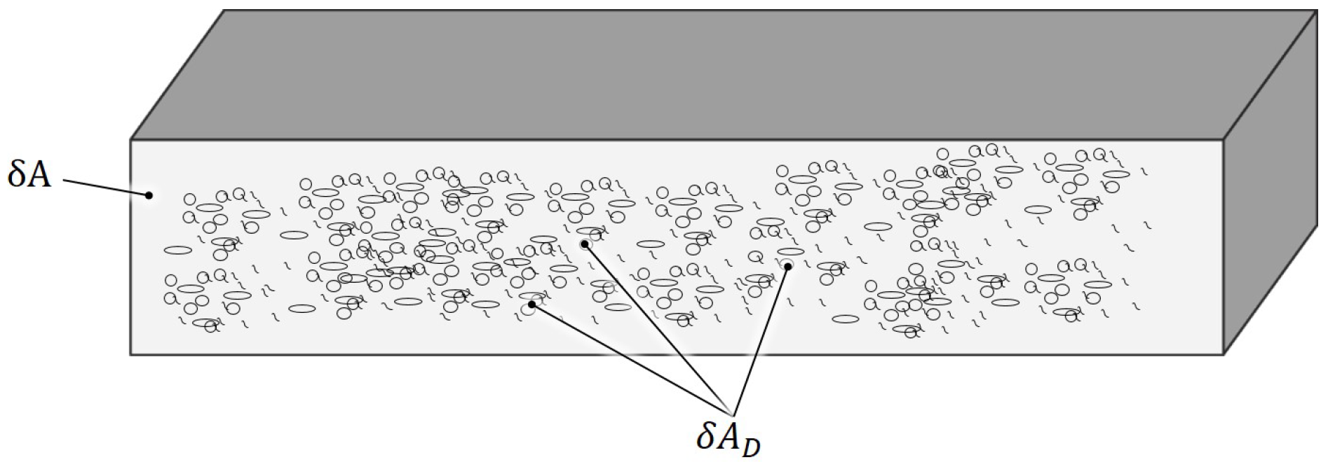
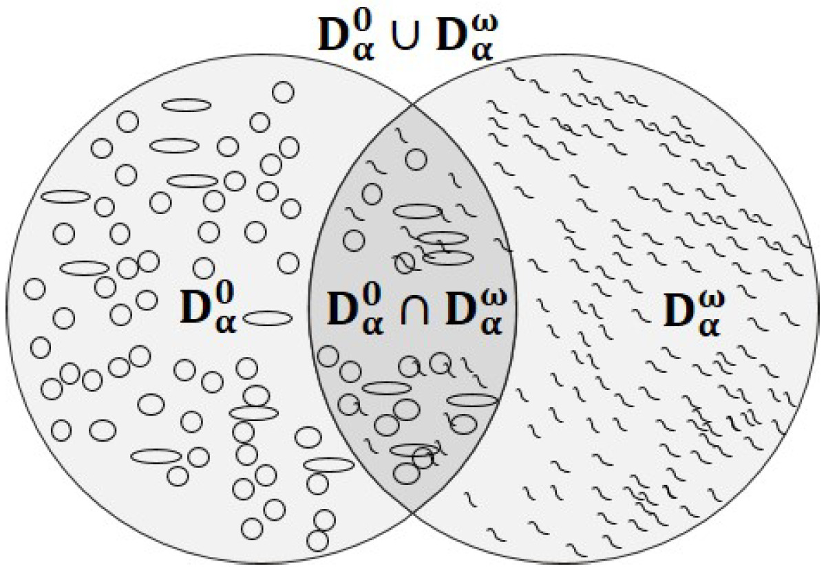
2.2. Adjunctive Damage Model

For the mathematical description of the strain-rate-dependent stress-strain behaviour of GF-MAG/EP composites under uniaxial tensile loading, an extended Hooke’s law according to
σ α ( ε ˙ ) = 1 D α ε ˙ · E α 0 ε ˙ · ε α α = 0 ° , 45 ° , 90 °
is used. Therein are σ α the nominal stress, D α ε ˙ the damage parameter, E α 0 the modulus of elasticity of the reference material, and ε α the strain. The variables are formulated as a function of the direction of loading α . In addition, the modulus of elasticity depends on the strain rate ε ˙ as observed from experiments.
The degree of damage in terms of the damage parameter D α ε ˙ is obtained by integration from the differential equation of damage evolution D ˙ α ε ˙ formulated according to [50] as follows
D ˙ α ε ˙ = κ α · ε ˙ + ξ α · ε ˙ λ α
with the strain rate ε ˙ and the free parameters κ α , ξ α , and λ α . For a constant strain rate, which can be assumed in good approximation for the tests carried out here, the degree of damage results to
D α ε ˙ = κ α + ξ α · ε ˙ λ α 1 ε α + D α χ .
The free parameters can be identified by adapting them to experimentally determined stress-strain curves. In [50], the resulting additive integration constant was set to zero ( D α χ = 0 ), since an ideal defect-free and non-preloaded textile composite material was assumed. As described in [8], this parameter can be understood as a defect parameter and enables the consideration of any pre-damage to the material. As preliminary investigations show, homogeneous damage to the composite can be assumed in the case of both voids [4] and fatigue [44]. If both types of defects are present in the material, they can influence each other [4] and must be taken into account in the mathematical description.
The evolved model presented here shows an approach that takes into account the defect interaction of voids and fatigue pre-damage with the help of the additive defect parameter D α χ . It is assumed in analogy to the continuum damage mechanics referring back to Kachanov and Rabotnov [54,55] that the damage D α χ in the uniaxial and isotropic case can be understood as the ratio of the damaged cross-sectional area δ A D and the nominal cross-sectional area δ A according to
D α χ = δ A D δ A .
The damage in the material can thus be quantified practically in a cross-section of the damaged body that is perpendicular to the direction of loading (Figure 2). The defect parameter D α χ is limited as follows
0 D α χ 1 .
As described above for an ideal defect-free and non-preloaded textile composite material, D α χ = 0 . As a result of the manufacturing-related defects in the form of homogeneously distributed voids, which are always present in practice, the integration constant reaches a value greater than zero ( D α 0 > 0 ). The integration constant is also greater than zero ( D α ω > 0 ), here specifically D c y > 0 , if additional general operational defects occur in the load history as a result of cyclic preloading. Defects caused by cyclic preloading are supposed to be homogeneously distributed.
With the findings from the characterisation of the defects carried out by means of in situ computed tomography in [4], it is concluded that fatigue-related inter-fibre fractures and production-related voids are two separate defects that might partially interact as well. The interaction of both defect types can be mathematically described from the geometric view according to Figure 3 as an adjunction ( D α 0 D α ω ) for the first time.
In summary, this results in the following cases:
D α 0 D α ω = 0 ideal pristine composite , D α 0 > 0 composite with manufacturing defects , D α ω > 0 composite with operational defects , D α 0 D α ω > 0 interaction of manufacturing and operational defects .
Assuming that manufacturing defects D α 0 and operational defects D α ω arise independently of each other, the probability that both defects occur simultaneously is equal to the product of the individual probabilities according to
D α 0 D α ω = D α 0 · D α ω .
The interaction of both defect types can be seen from Figure 3 as adjunctive formulation according to the damage caused by both defects and can thus be determined according to:
D α 0 D α ω = D α 0 + D α ω D α 0 D α ω .
The AND-term ( D α 0 D α ω ) must be subtracted from the sum of the two damage parameters, since both types of defects can overlap. For a few small defects, and thus small damage parameters, this portion is relatively small. However, if the number and size of defects increase, the probability of overlapping defects also increases; therefore, the influence of the AND term also increases.
Thus, Equations (8) and (9) result in the defect parameter D α χ , which represents the pre-damage of the material due to defects caused by manufacturing and operation according to
D α χ = D α 0 + D α ω D α 0 · D α ω .
The strain-rate-dependent damage behaviour of GF-NCF/EP-composites with sequential homogeneous pre-damage due to voids and multiple cracks can thus be described on a macroscopic level considering the adjunctive damage components with Equations (4) and (10) in a defect-dependent evolution equation according to
D α ε ˙ = κ α + ξ α · ε ˙ λ α 1 ε α + D α 0 + D α ω D α 0 · D α ω .
As described in many studies [1,2,50] and also proven by our own work on this material [8,28,52], an increase in stiffness can be observed with increasing load rate. Therefore, the direction-dependent elastic moduli are dependent on the strain rate ε ˙ . The experimentally observed non-linear stress-strain behaviour, without a description of material failure, can be described in practice with a Johnson-Cook model [56] adapted for FRP [50]:
E α 0 ( ε ˙ ) = E α 0 , r e f 1 + A α E · ln ε ˙ ε ˙ r e f .
Here, E α 0 , r e f are the direction-dependent engineering constants in the nominally undamaged state determined at a selected reference strain rate ε ˙ r e f and A α E is a material constant.
The combination of Equations (2), (4), (10) and (12) results in the mathematical description of the strain-rate-dependent stress-strain behaviour of defect-affected GF-NCF/EP-composites in the elementary case of an uniaxial load and neglecting the transverse contraction influence according to
σ α = 1 κ α + ξ α · ε ˙ λ α 1 ε α + D α 0 + D α ω D α 0 · D α ω · E α 0 , r e f 1 + A α E · ln ε ˙ ε ˙ r e f ε α ,
the Adjunctive Damage Model (ASM).

2.3. Parameter Identification

The direction-dependent material parameters and damage parameters present in the ASM can be determined from the test results by means of inverse identification using the method of least squares. Here, the model parameters were determined in tensile tests of GF/NCF-EP-composites in 0°-, 45°-, and 90°-loading direction in three steps. In steps one and two, results from nominally defect-free reference specimens are evaluated. The first step is to determine the direction-dependent engineering constants E α 0 , r e f at the lowest strain rate 0.0004 s 1 , as this corresponds to a quasi-static loading speed. For the mathematical description of the strain-rate dependence of the material behaviour, in step two, the tests at strain rates of 0.004 s 1 and 4 s 1 are used to determine the material and damage parameters. The defect parameter D α 0 is not necessarily set to zero during identification because voids are omnipresent. In contrast, cyclic pre-damage can be excluded for the nominally defect-free reference material, so that D α ω = 0 . Table 2 contains the determined directional constants and parameters. It can be seen that the defect parameter D α 0 increases with decreasing fibre content in the loading direction. The more the matrix dominates the mechanical material behaviour, the more an influence of voids is detectable.
Figure 4 shows the composite-specific comparison of the corresponding experimentally and computationally determined stress-strain curves as a function of the strain rate for the nominally defect-free reference materials. In the 0°-loading direction, an approximately linear curve can be seen, while the curves for the 45°- and 90°-loading direction show a non-linear stress-strain behaviour. The evaluation of the stress-strain diagrams consistently shows an increase in stiffness and strength with increasing loading rate. The presented model is thus flexible enough to represent the experimentally determined stress-strain curves of the nominally defect-free tensile specimens as a function of the strain rate with a uniform modelling approach.
In the third step, the results of the tensile tests determined on voids and pre-fatigued composites at the specified reference strain rate are used to determine the defect parameters (Table 3).
Figure 5 shows the experimental and calculated stress-strain-curves of the defective specimens in direct relation to the nominally defect-free reference tests. The investigated composite material degrades with increasing void contents and with higher pre-fatigue. A good agreement of the modelled curves with the experimentally determined stress-strain curves is recognisable. The degradation of the defective GF-NCF/EP-composites can be represented uniformly for the first time with the presented model approach. The applied step-by-step strategy for parameter identification enables the determination of the free parameters without complex non-linear optimisation.

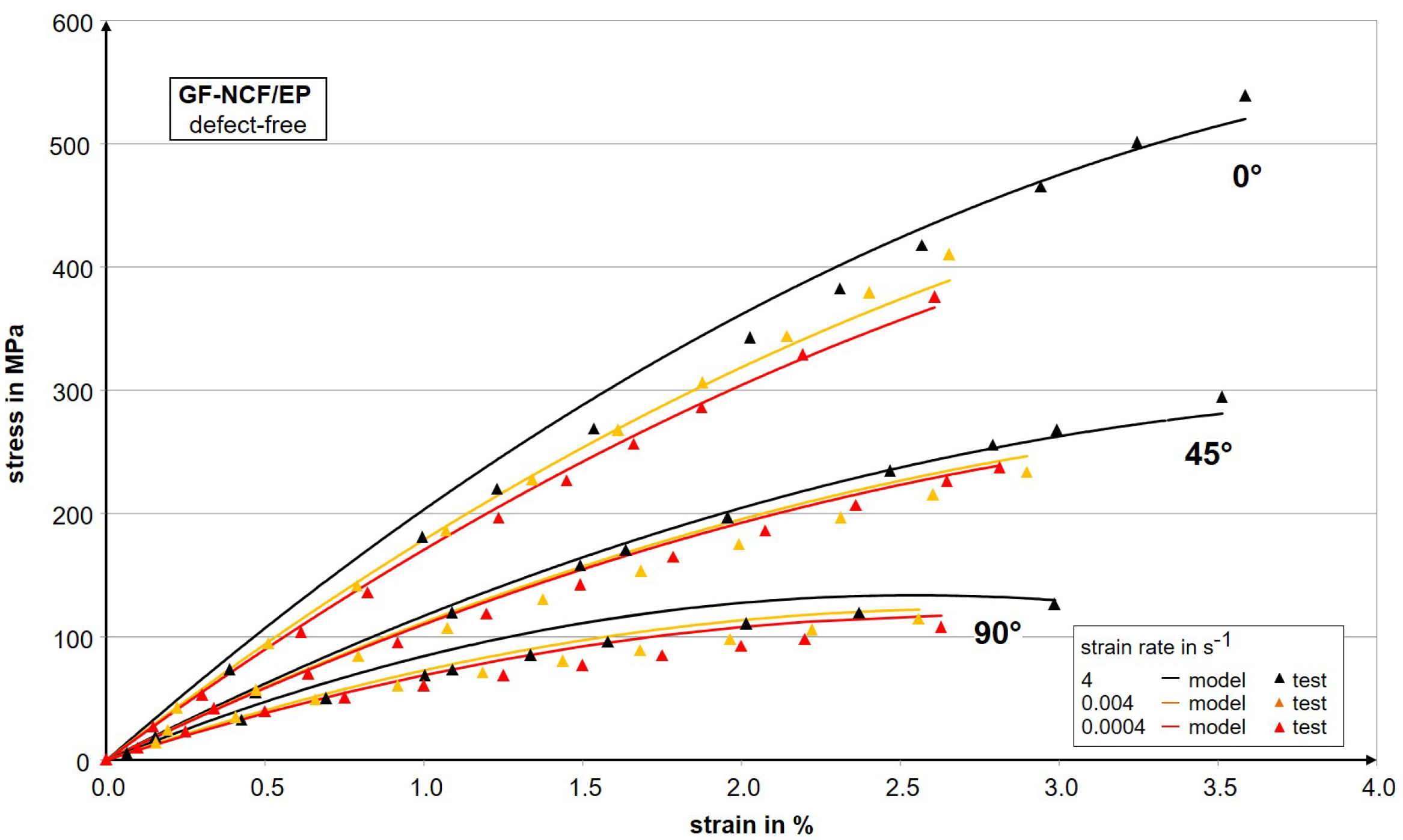
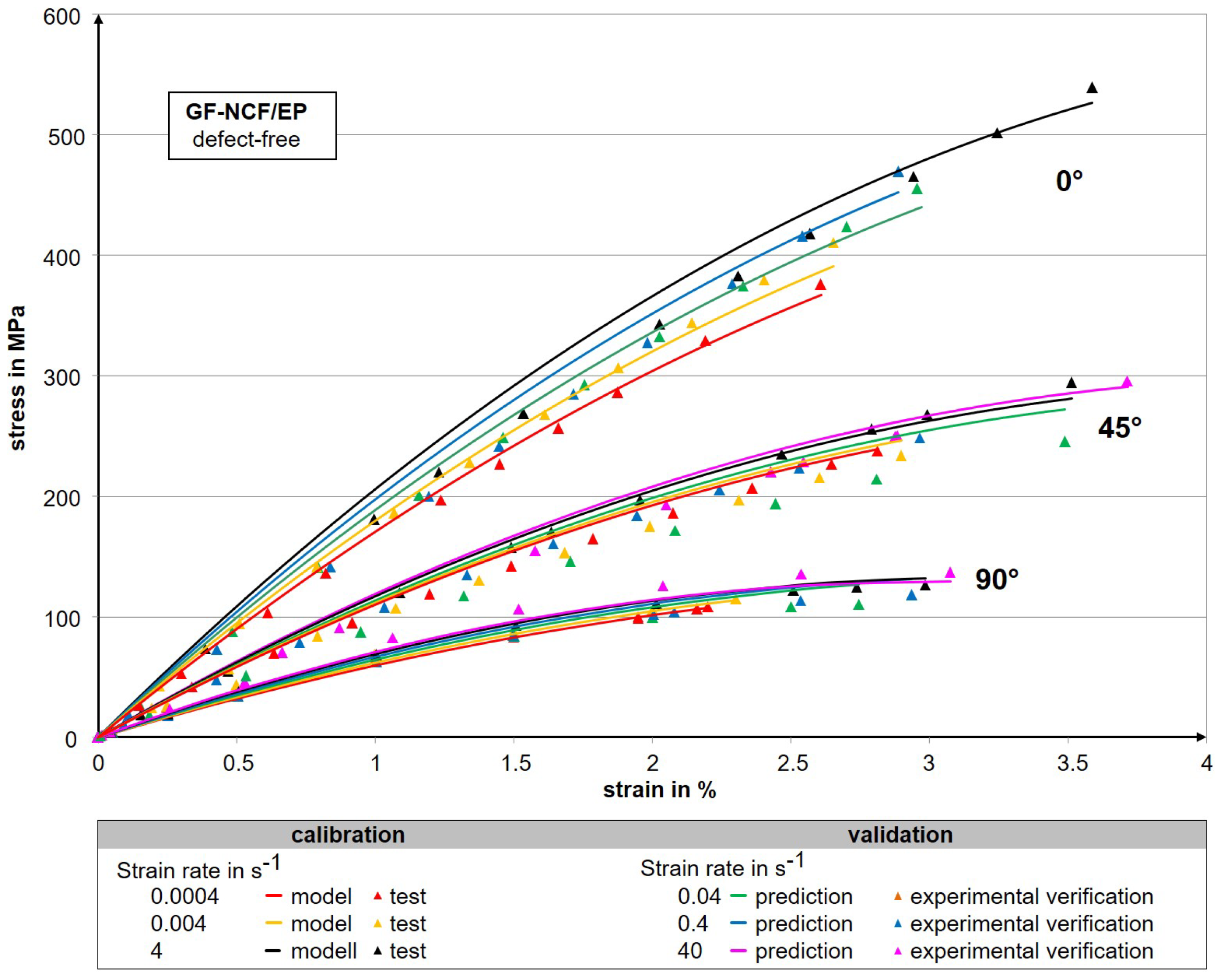
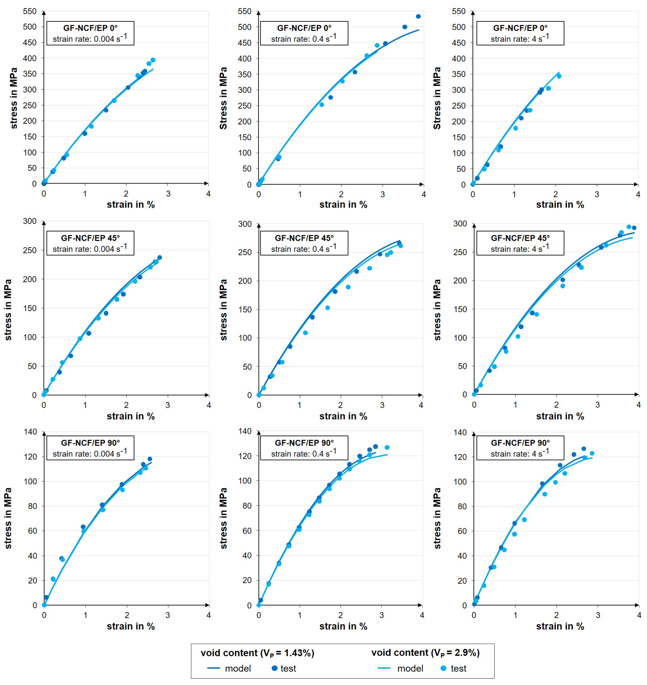
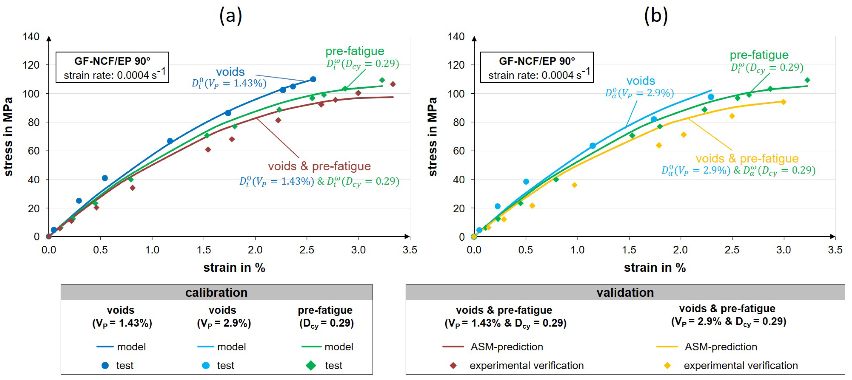
3. Results and Discussion

Model Validation

For model validation, the agreement of predicted curve shapes with further experimentally determined strain-rate-dependent stress-strain curves not used for calibration is checked. The agreement is evaluated on the basis of the mean relative deviation. In the first step, predictions of the stress-strain behaviour are checked for further strain rates of 0.04 s 1 , 0.4 s 1 , and 40 s 1 on the basis of the direction-dependent model parameters summarized in Table 2. The predicted curves are compared with the results of the highly dynamic tensile tests in Figure 6. The strain-rate-dependent stiffness increase, the linear curve progression in the 0°-loading direction, and the non-linear stress-strain behaviour in the 45°- and 90°- loading directions are well predicted. The average relative deviation between the test result and the model prediction is 8.6% for the 0°-loading direction, 13% for the 45°-loading direction, and 7.1% for the 90°-loading direction.
In the next step, the model parameters and the direction-dependent defect parameters for manufacturing-related defects ( D α 0 ) summarised in Table 3 are used. The purpose is used to predict the stress-strain behaviour of porous GF-NCF/EP composites with void contents of 1.43% and 2.9% as well as for strain rates of 0.004 s 1 , 0.4 s 1 , and 4 s 1 . As shown in Figure 7, the predicted curve shapes for porous composites in the 0°-, 45°-, and 90°-loading directions agree well with mean relative deviations of 9.2% (0°-loading direction), 8.6% (45°-loading direction), and 6.8% (90°-loading direction). The deviations between the model and the test can partially be attributed to variations in the determined void contents, which are not known for specific specimens.
Finally, on the basis of the separately determined defect parameters summarised in Table 2, the stress-strain curves are predicted for defective composites in which both defect types (voids and fatigue pre-damage) are simultaneously present. Figure 8 shows the curve progressions calculated by the ASM and the corresponding measured values for separately existing defects in form of voids with void contents of 1.43% (Figure 8a), of 2.9% (Figure 8b), or with fatigue-related pre-damage up to D c y = 0.29 . Here, predictions with a mean deviation of 9.7% were achieved. It can be concluded that pre-damage due to the interacting of voids and fatigue further reduces the strain-rate-dependent stiffness behaviour significantly.

4. Conclusions and Summary

Due to their adjustable energy absorption capacity, non-crimp fabric composites are predestined for lightweight structures that are exposed to high loads and thus high deformation rates under operating conditions. However, NCF-composites can exhibit defects that occur during production (voids) and in operation (fatigue). The influence of such defects, especially the interaction of both defect types on the strain-rate-dependent material behaviour, is still insufficiently researched and can represent a safety risk. In order to analyse the influence of separately or jointly present voids and fatigue pre-damage on the strain-rate-dependent material behaviour, the manufacturing process was modified. Furthermore, a test method was developed that makes it possible to determine defined fatigue-induced pre-damage in test specimens. The strain-rate-dependent material behaviour was analysed under tensile load at nominal technical strain rates of 0.0004 s 1 to 40 s 1 . For complete material mechanical characterisation, test specimens were tested in three fibre directions.
The experimental work indicates the need for combined modelling of the direction dependence of the properties, the strain-rate dependence and the interaction of the defects. For this purpose, the phenomenological Adjunctive Damage Model (ASM) with statistical considerations of the defect interaction was developed. The interaction of both defect types is formulated as an adjunctive operation (OR) of the defect parameters. With increasing defect sizes, and thus increasing defect interactions, the strain-rate-dependent deformation behaviour can be predicted more precisely than with a pure summation of both defect types. An essential advantage of the ASM lies in the prediction of the strain-rate-dependent degradation behaviour of composites with separate or combined manufacturing- and service-related defects for the first time.
The result is a flexible and practice-oriented model approach for the description of the strain-rate-dependent material behaviour. The knowledge gained makes a significant contribution to the future defect-tolerant design of FRP structural components, which can be used to reduce over dimensioning and uncertainties in product development and product use.

Author Contributions

Conceptualisation, R.P. and M.G.; methodology, R.P.; software, R.P.; validation, R.P. and M.G.; formal analysis, R.P. and I.K.; investigation, R.P. and I.K.; resources, M.G.; data curation, R.P.; writing—original draft preparation, R.P.; writing—review and editing, I.K. and M.G.; visualisation, R.P.; supervision, M.G. and I.K.; project administration, M.G.; funding acquisition, M.G. and R.P. All authors have read and agreed to the published version of the manuscript.

Funding

Funded by the German Research Foundation, projekt 428328210.

Data Availability Statement

Available on request.

Acknowledgments

The authors wish to express their thanks to the partner in these research project PAK988 “DIWA”.

Conflicts of Interest

The authors declare no conflict of interest.

References

  1. Gude, M.; Hufenbach, W.; Ebert, C. The strain-rate-dependent material and failure behaviour of 2D and 3D non-crimp glass-fibre-reinforced composites. Mech. Compos. Mater. 2009, 45, 467–476. [Google Scholar] [CrossRef]
  2. Gerritzen, J.; Hornig, A.; Gröger, B.; Gude, M. A Data Driven Modelling Approach for the Strain Rate Dependent 3D Shear Deformation and Failure of Thermoplastic Fibre Reinforced Composites: Experimental Characterisation and Deriving Modelling Parameters. J. Compos. Sci. 2022, 6, 318. [Google Scholar] [CrossRef]
  3. Mehdikhani, M.; Gorbatikh, L.; Verpoest, I.; Lomov, S.V. Voids in fiber-reinforced polymer composites: A review on their formation, characteristics, and effects on mechanical performance. J. Compos. Mater. 2019, 53, 1579–1669. [Google Scholar] [CrossRef]
  4. Protz, R.; Koch, I.; Gude, M. In-situ computer tomography for analyzing the effect of voids on the damage behavior of composite materials. IOP Conf. Ser. Mater. Sci. Eng. 2018, 406, 012013. [Google Scholar] [CrossRef]
  5. Kulkarni, P.; Mali, K.D.; Singh, S. An overview of the formation of fibre waviness and its effect on the mechanical performance of fibre reinforced polymer composites. Compos. Part A 2020, 137, 106013. [Google Scholar] [CrossRef]
  6. Drummer, J.; Tafesh, F.; Fiedler, B. Effect of Fiber Misalignment and Environmental Temperature on the Compressive Behavior of Fiber Composites. Polymers 2023, 13, 2833. [Google Scholar] [CrossRef]
  7. Schmidt, F. Defekteinflüsse bei Faser-Kunststoff-Verbunden unter Multiaxialer Belastung. Ph.D. Thesis, Technische Universität Braunschweig, Braunschweig, Germany, 2013. [Google Scholar]
  8. Hufenbach, W.; Gude, M.; Protz, R. Modeling of the strain rate dependent material behavior of 3D-textile composites with production and operational defects. Adv. Mater. Res. 2012, 403, 651–655. [Google Scholar] [CrossRef]
  9. Wu, X.F.; Zholobko, O. Experimental study of the probabilistic fatigue residual strength of a carbon fiber-reinforced polymer matrix composite. J. Compos. Sci. 2020, 4, 173. [Google Scholar] [CrossRef]
  10. Witzgall, C.; Steck, P.; Wartzack, S. On the Influence of Fatigue Damage in Short-Fibre Reinforced Thermoplastic PBT GF30 on Its Residual Strength under High Strain Rates: An Approach towards Simulative Prediction. J. Compos. Sci. 2023, 7, 23. [Google Scholar] [CrossRef]
  11. Abrate, S. Composite structures: Impact on composites. Compos. Struct. 2003, 61, 309–334. [Google Scholar] [CrossRef]
  12. Kristnama, A.R.; Xu, X.; Nowell, D.; Wisnom, M.R.; Hallett, S.R. Experimental investigation of high velocity oblique impact and residual tensile strength of carbon/epoxy laminates. Compos. Sci. Technol. 2019, 182, 107772. [Google Scholar] [CrossRef]
  13. Bogenfeld, R.; Gorsky, C. An experimental study of the cyclic compression after impact behavior of CFRP composites. J. Compos. Sci. 2021, 5, 296. [Google Scholar] [CrossRef]
  14. Fu, Y.; Yao, X.; Gao, X. Micro-mesoscopic prediction of void defect in 3D braided composites. Compos. Part A Appl. Sci. Manuf. 2021, 147, 106450. [Google Scholar] [CrossRef]
  15. Talreja, R. Effects of manufacturing induced defects on composite damage and failure. Polym. Compos. Mater. Wind. Power Turbines 2006, 83–96, ISBN 87-550-3528-0. [Google Scholar]
  16. Gehrig, F. Einfluss von Poren auf das Schädigungsverhalten von kohlenstofffaserverstärkten Kunststoffen. Ph.D. Thesis, Technische Universität Hamburg-Harburg, Hamburg, Germany, 2011. [Google Scholar]
  17. Grunenfelder, L.K.; Nutt, S.R. Void formation in composite prepregs-Effect of dissolved moisture. Compos. Sci. Technol. 2010, 70, 2304–2309. [Google Scholar] [CrossRef]
  18. Alves, F.C.; Monticeli, F.M.; Neves, R.M.; Voorwald, H.J.C.; Cioffi, M.O.H.; Ornaghi, H.L. Influence of void content and morphology on the creep behavior on glass/epoxy composites. Compos. Commun. 2021, 25, 100712. [Google Scholar] [CrossRef]
  19. Kreikemeier, J.; Chrupalla, D.; Khattab, I.A.; Krause, D. Experimentelle und Numerische Untersuchungen von CFK mit Herstellungsbedingten Fehlstellen. In 10. Magdeburger Maschinenbautage. 2011. Available online: https://elib.dlr.de/71096/ (accessed on 27 August 2023).
  20. Quaresimin, M.; Susmel, L.; Talreja, R. Fatigue behaviour and life assessment of composite laminates under multiaxial loadings. Int. J. Fatigue 2010, 32, 2–16. [Google Scholar] [CrossRef]
  21. Schell, J.S.U.; Deleglise, M.; Binetruy, C.; Krawczak, P.; Ermanni, P. Numerical prediction and experimental characterisation of meso-scale-voids in liquid composite moulding. Compos. Part A 2007, 38, 2460–2470. [Google Scholar] [CrossRef]
  22. Ornaghi, H.L.; Monticeli, F.M.; Neves, R.M.; Zattera, A.J.; Cioffi, M.O.H.; Voorwald, H.J.C. Effect of stacking sequence and porosity on creep behavior of glass/epoxy and carbon/epoxy hybrid laminate composites. Compos. Commun. 2020, 19, 210–219. [Google Scholar] [CrossRef]
  23. Kosmann, N.; Karsten, J.M.; Schuett, M.; Schulte, K.; Fiedler, B. Determining the effect of voids in GFRP on the damage behaviour under compression loading using acoustic emission. Compos. Part B 2015, 70, 184–188. [Google Scholar] [CrossRef]
  24. Ashir, M.; Nocke, A.; Bulavinov, A.; Pinchuk, R.; Cherif, C. Influence of defined amount of voids on the mechanical properties of carbon fiber-reinforced plastics. Polym. Compos. 2018, 40, 1049–1056. [Google Scholar] [CrossRef]
  25. Varna, J.; Joffe, R.; Berglund, L.A.; Lundström, T.S. Effect of voids on failure mechanisms in RTM laminates. Compos. Sci. Technol. 1995, 53, 241–249. [Google Scholar] [CrossRef]
  26. Schmidt, F.; Rheinfurth, M.; Horst, P.; Busse, G. Multiaxial fatigue behaviour of GFRP with evenly distributed or accumulated voids monitored by various NDT methodologies. Int. J. Fatigue 2012, 43, 207–216. [Google Scholar] [CrossRef]
  27. Maragoni, L.; Carraro, P.A.; Peron, M.; Quaresimin, M. Fatigue behaviour of glass/epoxy laminates in the presence of voids. Int. J. Fatigue 2017, 95, 18–28. [Google Scholar] [CrossRef]
  28. Protz, R.; Kosmann, N.; Gude, M.; Hufenbach, W.; Schulte, K.; Fiedler, B. Voids and their effect on the strain rate dependent material properties and fatigue behaviour of non-crimp fabric composites materials. Compos. Part B 2015, 83, 346–351. [Google Scholar] [CrossRef]
  29. Sisodia, S.M.; Garcea, S.C.; George, A.R.; Fullwood, D.T.; Spearing, S.M.; Gamstedt, E.K. High-resolution computed tomography in resin infused woven carbon fibre composites with voids. Compos. Sci. Technol. 2016, 131, 12–21. [Google Scholar] [CrossRef]
  30. Hyde, A.; He, J.; Cui, X.; Lua, J.; Liu, L. Effects of microvoids on strength of unidirectional fiber-reinforced composite materials. Compos. Part B 2020, 187, 107844. [Google Scholar] [CrossRef]
  31. Gao, X.; Yuan, L.; Fu, Y.; Yao, X.; Yang, H. Prediction of mechanical properties on 3D braided composites with void defects. Compos. Part B 2020, 197, 108164. [Google Scholar] [CrossRef]
  32. Wang, K.; Lu, Y.; Rao, Y.; Wei, N.; Ban, J.; Peng, Y.; Yao, S.; Ahzi, S. New insights into the synergistic influence of voids and interphase characteristics on effective properties of unidirectional composites. Compos. Struct. 2021, 255, 112862. [Google Scholar] [CrossRef]
  33. Suhot, M.A. The Effect of Voids on the Flexural Fatigue Properties of Carbon/Epoxy Composites. Ph.D. Thesis, University of Southampton, Southampton, UK, 2010. [Google Scholar]
  34. Huang, H.; Talreja, R. Effects of void geometry on elastic properties of unidirectional fiber reinforced composites. Compos. Sci. Technol. 2005, 65, 1964–1981. [Google Scholar] [CrossRef]
  35. Vajari, D.A.; González, C.; Llorca, J.; Legarth, B.N. A numerical study of the influence of microvoids in the transverse mechanical response of unidirectional composites. Compos. Sci. Technol. 2014, 97, 46–54. [Google Scholar] [CrossRef]
  36. Gao, J.; Yuan, Y. Probabilistic modeling of stiffness degradation for fiber reinforced polymer under fatigue loading. Eng. Fail. Anal. 2020, 116, 104733. [Google Scholar] [CrossRef]
  37. Li, P.; Yao, W.; Chen, F.; Zong, J. Residual stiffness characterization of FRP laminates under random block spectrum. Polym. Test. 2021, 95, 107101. [Google Scholar] [CrossRef]
  38. Pakdel, H.; Mohammadi, B. Stiffness degradation of composite laminates due to matrix cracking and induced delamination during tension-tension fatigue. Eng. Fract. Mech. 2019, 216, 106489. [Google Scholar] [CrossRef]
  39. Epaarachchi, J.A.; Clausen, P.D. A new cumulative fatigue damage model for glass fibre reinforced plastic composites under step/discrete loading. Compos. Part A 2005, 36, 1236–1245. [Google Scholar] [CrossRef]
  40. Philippidis, T.P.; Passipoularidis, V.A. Residual strength after fatigue in composites: Theory vs. experiment. Int. J. Fatigue 2007, 29, 2104–2116. [Google Scholar] [CrossRef]
  41. Böhm, R. Bruchmodebezogenen Beschreibung des Degradationsverhaltens textilverstärkter Verbundwerkstoffe. Ph.D. Thesis, Technische Universität Dresden, Dresden, Germany, 2008. [Google Scholar]
  42. D’amore, A.; Grassia, L. Principal features of fatigue and residual strength of composite materials subjected to constant amplitude (CA) loading. Materials 2019, 12, 2586. [Google Scholar] [CrossRef]
  43. Matzenmiller, A.; Lubliner, J.; Taylor, R.L. A constitutive model for anisotropic damage in fiber-composites. Mech. Mater. 1995, 20, 125–152. [Google Scholar] [CrossRef]
  44. Koch, I. Modellierung des Ermüdungsverhaltens Textilverstärkter Kunststoffe. Ph.D. Thesis, Technische Universität Dresden, Dresden, Germany, 2010. [Google Scholar]
  45. Shokrieh, M.M.; Lessard, L.B. Fatigue under multiaxial stress systems. In Fatigue in Composites; Harris, B., Ed.; Woodhead Publishing: Sawston, UK, 2003; pp. 63–113. [Google Scholar]
  46. Withworth, H.A. Evaluation of the residual strength degradation in composite laminates under fatigue loading. Compos. Struct. 2000, 48, 261–264. [Google Scholar] [CrossRef]
  47. Broutman, L.; Sahu, S. A new theory to predict cumulative fatigue damage in fiberglass reinforced plastics. In Composite Materials: Testing and Design (Second Conference), STP27746S; Corten, H., Ed.; ASTM International, West Conshohocken: Conshohocken, PA, USA, 1972; pp. 170–188. [Google Scholar]
  48. Ebert, C. Werkstoffmechanische Modellierung von Textilverstärkten Thermoplastverbunden unter Hochdynamischer Belastung. Ph.D. Thesis, Technische Universität Dresden, Dresden, Germany, 2010. [Google Scholar]
  49. Zscheyge, M. Zum Temperatur- und Dehnratenabhängigen Deformations- und Schädigungsverhalten von Textil-Thermoplast-Verbunden. Ph.D. Thesis, Technische Universität Dresden, Dresden, Germany, 2015. [Google Scholar]
  50. Song, B.; Chen, W.; Weerasooriya, T. Quasi-static and dynamic compressive behaviors of a S-2 glass/SC15 composite. J. Compos. Mater. 2003, 37, 1723–1743. [Google Scholar] [CrossRef]
  51. Thiruppukuzhi, S.V.; Sun, C.T. Models for the strain-rate-dependent behavior of polymer composites. J. Compos. Sci. Technol. 2001, 61, 1–12. [Google Scholar] [CrossRef]
  52. Protz, R. Zum Einfluss von Defekten auf das Dehnratenabhängige Werkstoffverhalten von Faser-Kunststoff-Verbunden. Ph.D. Thesis, Technische Universität Dresden, Dresden, Germany, 2021. [Google Scholar]
  53. Just, G.; Koch, I.; Gude, M. Experimental Analysis of Matrix Cracking in Glass Fiber Reinforced Composite Off-Axis Plies under Static and Fatigue Loading. Polymers 2022, 14, 2160. [Google Scholar] [CrossRef] [PubMed]
  54. Kachanov, L.M. On the creep fracture time. Izv. Akad. Nauk SSR Otd. Tekhn. Nauk 1958, 8, 26–31. [Google Scholar]
  55. Rabotnov, Y.N. Creep rupture. In Proceedings of the 12th International Congress on Applied Mechanics, Stanford, CA, USA, 26–31 August 1968. [Google Scholar]
  56. Johnson, G.R.; Cook, W.H. Fracture characteristics of three metals subjected to various strains, strain rates, temperatures and pressures. Eng. Fract. Mech. 1985, 21, 31–48. [Google Scholar] [CrossRef]
Figure 1. Selected micrographs of nominally void-free (a), with low void content (b) and with higher void content (c) GF-NCF/EP test specimens.
Jcs 07 00365 g001
Figure 2. Principle representation of homogeneously distributed manufacturing and operational defects.
Jcs 07 00365 g002
Figure 3. Geometric consideration of the interaction of manufacturing and operational defects.
Jcs 07 00365 g003
Figure 4. Comparison of representative strain-rate-dependent stress-strain-curves from experimentally determined and computationally generated data for nominally defect-free GF-MAG/EP composites for parameter identification.
Jcs 07 00365 g004
Figure 5. Comparison of representative stress-strain curves determined experimentally and with the identified parameters calculated stress-strain curves of nominally defect-free, porous and pre-fatigued GF-MAG/EP- composites at the reference strain rate.
Jcs 07 00365 g005
Figure 6. Validation of the ASM for additional strain rates for nominal defect-free GF-NCF/EP-composites for strain rates of 0.04 s 1 , 0.4 s 1 and 40 s 1 .
Jcs 07 00365 g006
Figure 7. Validation of the strain-rate-dependent stress-strain curves of porous GF-NCF/EP-composites calculated with the ASM.
Jcs 07 00365 g007
Figure 8. Validation of the material behaviour of defective GF-NCF/EP-composites with separately and simultaneously existing operational defects D c y = 0.29 and manufacturing defects with V P = 1.43 % (a) and V P = 2.9 % (b).
Jcs 07 00365 g008
Table 1. Process parameters for specimens production of GF-NCF/EP-composites.
Void ContentMax. Injection PressureVacuumHolding PressureDegassing
0.01 ± 0.01%3−13Yes
1.43 ± 0.65%0.5−0.40No
2.9 ± 0.9%1−0.20No
Table 2. Identified model parameters for the description of the strain-rate-dependent material behaviour of nominally defect-free GF-NCF/EP-composites.
Parameter90°45°
E α 0 , r e f in GPa8.412.418.9
ε ˙ r e f in s 1 0.00040.00040.0004
A α E 0.020.010.02
ξ α 2.240.20.06
λ α 1.1211.7
κ α 10119.8
D α 0 0.170.0010
D α ω 000
Table 3. Identified model parameters for the description of the strain-rate-dependent material behaviour of defective GF-NCF/EP-composites.
Defect ParameterDefect Measure90°45°
D α 0 V P = 1.43 % 0.210.0250.039
D α 0 V P = 2.9 % 0.220.040.046
D α ω D c y = 0.29 0.1-/- 1-/-
D α ω D c y = 0.42 0.17-/--/-
1 not yet determined.
Disclaimer/Publisher’s Note: The statements, opinions and data contained in all publications are solely those of the individual author(s) and contributor(s) and not of MDPI and/or the editor(s). MDPI and/or the editor(s) disclaim responsibility for any injury to people or property resulting from any ideas, methods, instructions or products referred to in the content.

